

Construction of Multispectral False-Color Images Using Ultraviolet-Induced Fluorescence and Reflected Ultraviolet Imaging
Expanding Visual Identification in Painting Analysis
31st JSCCP Annual Meeting
⚪︎S Hamaya
Introduction
In the field of conservation and restoration, the use of ultraviolet and infrared false-color imaging for assessing the condition of paintings has been widely studied, and numerous effective case studies have been reported.*1 However, there has been no systematic investigation into the technical feasibility of incorporating ultraviolet fluorescence imaging―commonly used in condition assessments―as a component in the reconstruction of false-color images.
In this study, an attempt was made to synthesize a multispectral false color image by combining three types of images taken for the purpose of image composition: visible light, reflected ultraviolet, and ultraviolet fluorescence. visible light, reflected ultraviolet, and ultraviolet fluorescence. The results demonstrate that this method enables the extraction of new visual information based on the optical responses of materials, which differs from that obtained through traditional ultraviolet and infrared false-color imaging.
By revealing the distribution of constituent materials within the painting―information that is often difficult to discern under visible light―this new approach to constructing false-color images offers promising potential for structural analysis and the assessment of conservation conditions.
Background
To prepare the component images for constructing a false-color composite, visible light photography, ultraviolet fluorescence photography, and reflected ultraviolet photography were conducted using black-and-white silver halide film (Photos 1a, b, c). For both ultraviolet fluorescence and reflected ultraviolet imaging, UV fluorescent lamps (TOSHIBA FL20S BLB) were used as light sources, while for visible light imaging, VITA-LITE®―a light source with a spectral distribution similar to natural sunlight―was employed. By standardizing all light sources to fluorescent types across different spectral bands, it became possible to minimize image discrepancies and disruptions during compositing due to differences in light source types or illumination methods (Table 1).
Following photography, negatives showing identical density values on the attached gray scale were selected for each imaging type. These were scanned and converted into digital image data with uniform resolution. Using image editing software, the three types of images―visible, reflected UV, and UV fluorescence―were assigned to the RGB channels to create the false-color composite (Photo 2). This procedure follows conventional methods for generating infrared/ultraviolet false-color images [*2] [*3] [*4].
There are six possible combinations for assigning images to the RGB channels. However, the most effective channel arrangement for visual discrimination during condition assessment depends on the distribution and techniques of the constituent materials used in the artwork (Table 2).
List of Figures
Figure 1.a, b, c: Various Monochrome Images Constituting the Components of the False Color Image
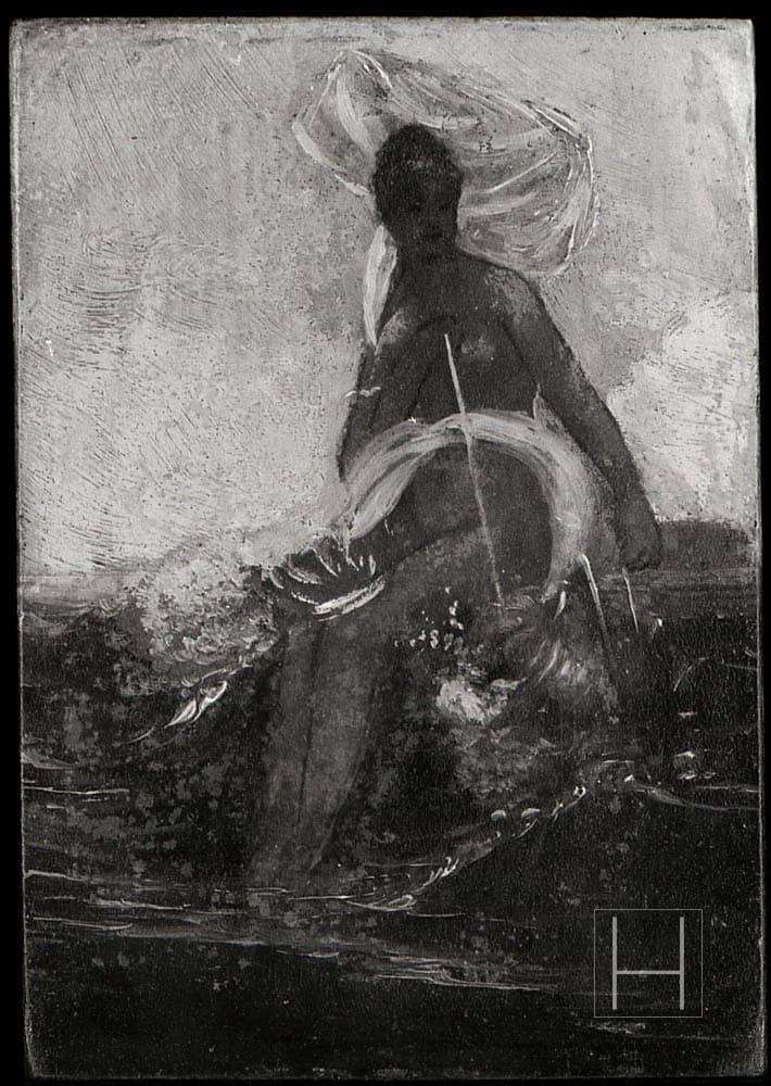
Figure 1.a. Visible light image
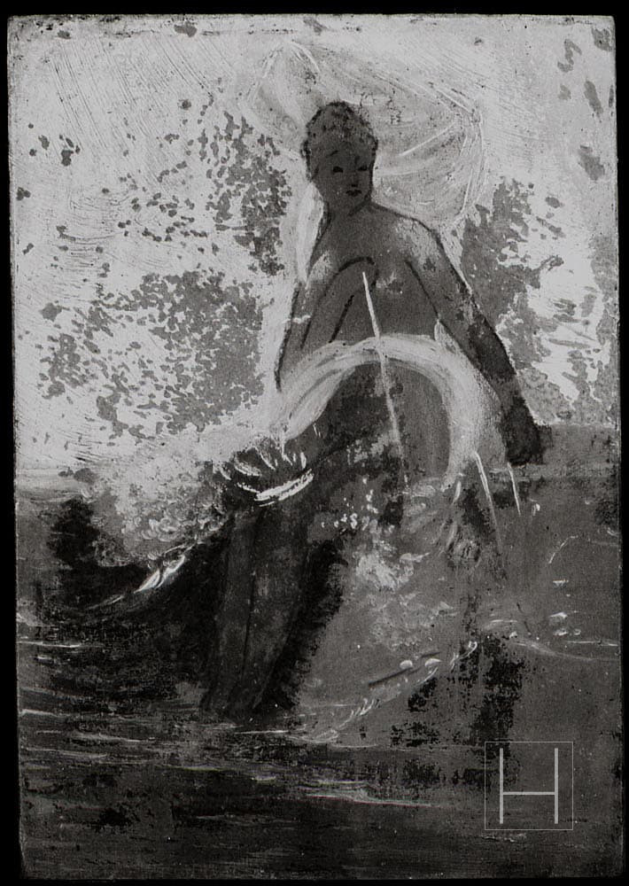
Figure 1.b. Ultraviolet fluorescence image
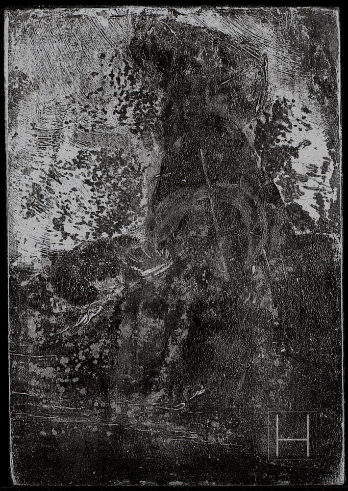
Figure 1.c. Reflected ultraviolet image
Table 1. Overview of Imaging Conditions
| Type of Imaging | Light Source | Applied Filter |
| Visible Light Imaging | VITE-LITE® 18Wx4 (5500K) | N/F* |
| Ultraviolet Fluorescence Imaging | TOSHIBA FL20S BLB 20W: x4 | Kodak Wratten No.2E |
| Reflected Ultraviolet Imaging | TOSHIBA FL20S BLB 20W: x4 | HOYA-U360 (360 nm) |
Lens: Tochigi Nikon UV-105mm f/4.5
Film: ILFORD DELTA 100 (Development: TMX RS Normal Process)
Note: The same light fixture was used for all imaging, with only the fluorescent tubes replaced. The angle and distance of illumination were kept constant.
Table 2. Overview of Image Reallocation to RGB Channels
| Source Image | Reallocation to RGB channels | |||||
| Visible light image | R | R | G | G | B | B |
| UV fluorescence image | G | B | R | B | R | G |
| Reflected UV image | B | G | B | R | G | R |
Abbreviations: R = Red channel, G = Green channel, B = Blue channel
Note:
The most effective RGB channel configuration for analysis depends on the distribution and techniques of the materials used in the artwork.
In Photo 2, the following configuration was adopted, based on the order of wavelength distribution:
Visible light image → Red channel,
UV fluorescence image → Green channel,
Reflected UV image → Blue channel
Figure 2. Multispectral Ultraviolet False Color Image
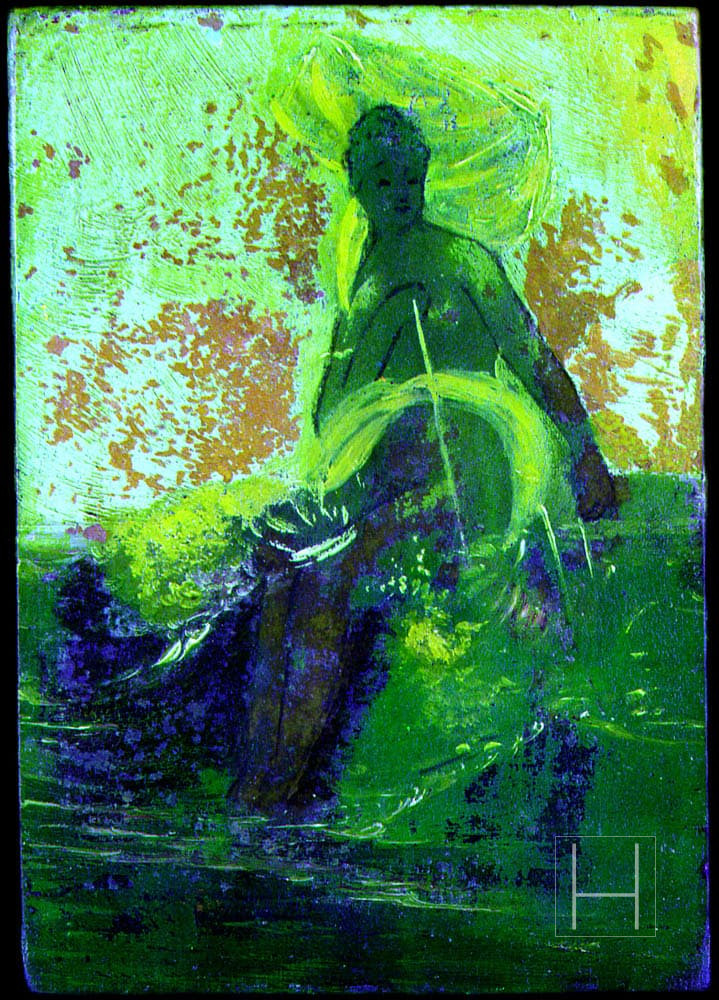
Figure 2 presents a false color image constructed by assigning the visible light image to the red channel, the ultraviolet fluorescence image to the green channel, and the ultraviolet reflectance image to the blue channel.
This composite image enables the identification of varnish layer distributions and differences in the composition of retouching pigments, which are challenging to discern under visible light alone.
Notably, distinct color variations corresponding to different white pigments—such as lead white, zinc white, and titanium white—are evident in the false color image, suggesting its effectiveness in differentiating these materials.
Furthermore, materials that exhibit subdued fluorescence and appear dark in ultraviolet fluorescence images can still be distinguished in the false color composite due to variations in color reproduction.
By comparing this image with other captured images, a more accurate understanding of the distribution and structure of materials can be achieved.
Future work will focus on systematically collecting response data of painting materials to establish new reference indicators.
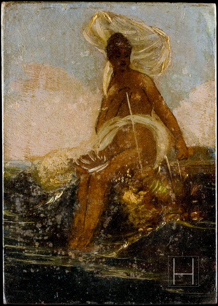
Figure 3. Visible light image
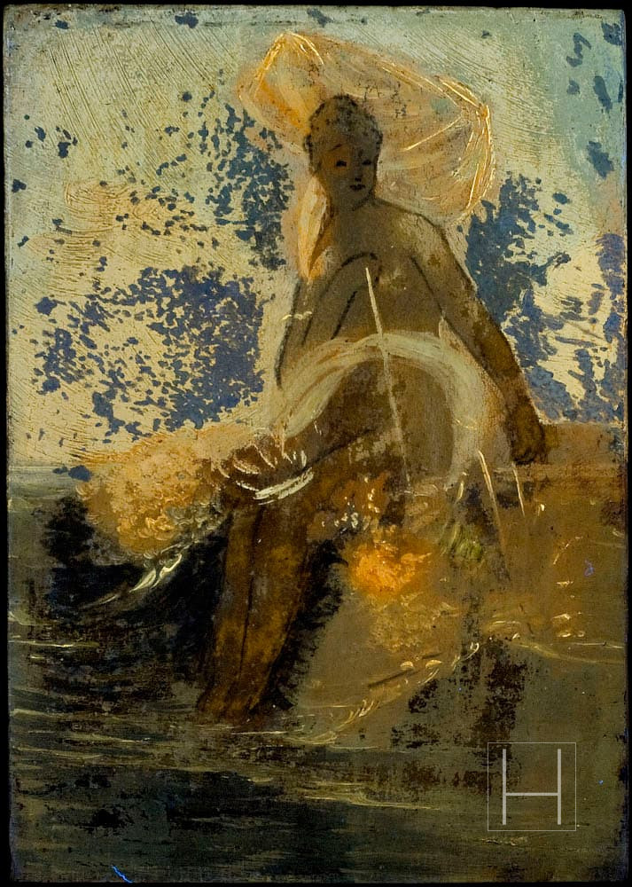
Figure 4. Ultraviolet fluorescence image
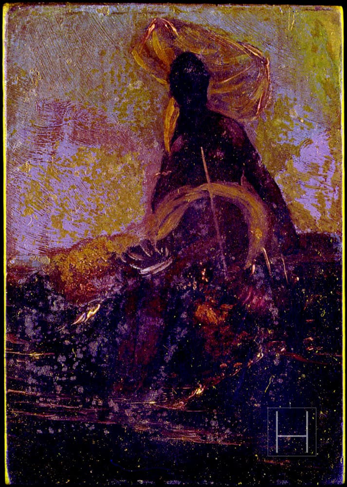
Figure 5. Ultraviolet false color image
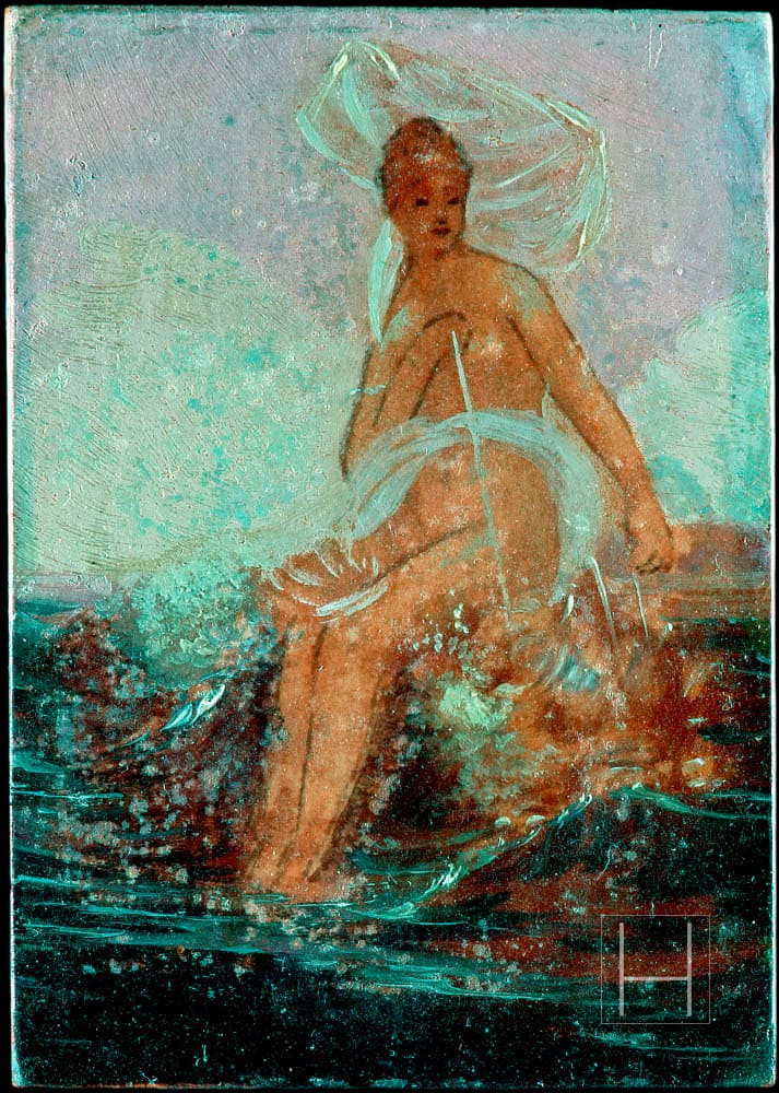
Figure 6. Infrared false color image
Reference Images and Captions
Photo 4. Ultraviolet fluorescence image
In ultraviolet fluorescence images, the intensity of the fluorescent reaction tends to increase with the aging of organic materials contained in the painting materials. However, this is largely influenced by the composition of mixed pigments, making chronological analysis of material distribution based solely on fluorescence intensity difficult. Furthermore, overlapping fluorescence reactions from upper and lower layers can interfere visually, making comparative analysis with other imaging techniques necessary.
Photo 5. Ultraviolet false color image
Reflectance ultraviolet images allow confirmation of surface details that are difficult to discern in the visible or infrared ranges. However, if high-refractive-index resins or binders are distributed on the surface, it becomes difficult to identify underlying structures. While most pigments show limited contrast in monochromatic reflectance UV images, different white pigments can be identified. Lead white appears as a strong white tone, while zinc white and titanium white are reproduced as different densities in grayscale. In ultraviolet false color images, when the ultraviolet element is assigned to the blue channel in an RGB image, non-lead white pigments appear in varying intensities of yellow, making identification more effective.
Photo 6. Infrared false color image
Infrared false color images are generally composed by assigning infrared elements to the red channel of an RGB image. They are effective in identifying distributions of pigments with different compositions that may appear visually identical in the visible spectrum.
| Image | Applied Filter | Light Source |
| Photo 3. Visible light image | B+W UV/IR-CUT | Profoto Pro 5 PB head 1500W: x2 |
| Photo 4. Ultraviolet fluorescence image | Kodak Wratten No.12 + B+W UV/IR-CUT | Toshiba FL20S BLB 20W: x4 |
| Photo 5. Ultraviolet false color image | B+W UV/IR-CUT (Visible component) | Profoto Pro 5 PB head 1500W: x2 |
| Hoya U-360 (UV component) | Toshiba FL20S BLB 20W: x4 | |
| Photo 6. Infrared false color image | B+W UV/IR-CUT (Visible component) | Profoto Pro 5 PB head 1500W: x2 |
| Kodak Wratten No.87 (IR component) |
Kodak DCS760/ Tochighi Nikon UV 105 mm *
Photography and Image Data Editing
The photography and image data editing were carried out at the request of the National Institute of Information and Communications Technology (NICT), with the aim of producing photographic materials of Italian classical paintings for terahertz spectroscopy.
Summary and Discussion
This study confirmed that the composite color images created from multispectral monochrome images allow for visual identification of the distribution of pigments with different compositions, which is difficult to discern under visible light alone.
In particular, it was demonstrated that even pigment layers located beneath varnish―often difficult to distinguish in ultraviolet fluorescence or reflected ultraviolet images―can be more clearly recognized through the use of these composite images.
Among these, white pigments showed distinct differences in optical responses depending on their composition in both ultraviolet fluorescence and reflected ultraviolet images. Furthermore, in cases where multiple white pigments of different compositions coexist within a single area, and reactions from varnish layers or binding media interfere with interpretation, the use of composite images as supplementary references made pigment identification easier and contributed to improved informational accuracy.
In the future, we aim to establish a more systematic identification framework based on these composite images by continuing to collect optical response data from reference samples of pigments and binding media used in paintings.
Note on Publication jsccp.or.jp
This article is based on the research titled “Proposal of Multispectral Ultraviolet Imaging Utilizing Ultraviolet Fluorescence Images,” presented during the poster session at the 31st Annual Meeting of the Japan Society for the Conservation of Cultural Property (June 13–14, 2009, Kurashiki Geibunkan). It has been restructured and published by the author for non-commercial informational purposes.
References
- A. Aldrovandi, E. Buzzegoli, A. Keller, D. Kunzelman, Il falso d’autore indagato con tecniche non invasive. Rapporto preliminare sulle indagini svolte in Santa Maria della Scala di Siena durante la mostra “Falsi d’autore”, OPD Restauro, n. 17, 2005, pp. 265–272.
- A. Aldrovandi, E. Buzzegoli, A. Keller, D. Kunzelman, Indagini su superfici dipinte mediante immagini UV riflesse in falso colore, OPD Restauro, n. 16, 2004, pp. 83–87.
- A. Aldrovandi, R. Bellucci, D. Bertani, E. Buzzegoli, M. Cetica, D. Kunzelmann, La ripresa in infrarosso falso colore: nuove tecniche di utilizzo, OPD Restauro, n. 5, 1993, pp. 94–98.
- R. Williams, G. Williams, Medical and Scientific Photography: An Online Resource for Doctors, Scientists, and Students, available at: https://www.medicalphotography.com.au/ (accessed April , 2009).